HW 4 - MOSFET Layout and Capacitances, NMOS Inverter-Dynamic Characteristics
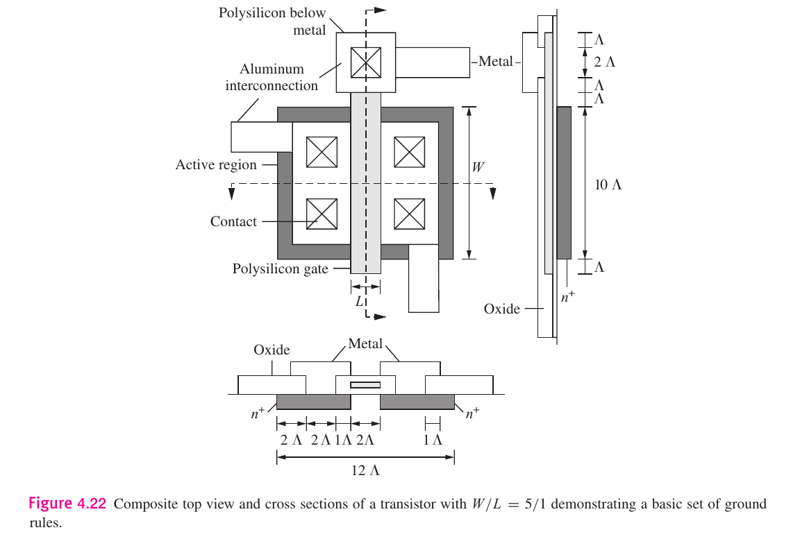
4.1, 4.5-4.6: MOSFET Layout and Capacitances
4.2
We know that:
thus, using :
| Part |
|
| a |
|
| b |
|
| c |
|
| d |
|
4.3
Using:
so using and we get:
4.65
We know that:
where , so plug in our values of and :
| Part |
|
|
|
| a |
|
|
|
| b |
|
|
|
| c |
|
|
|
| d |
|
|
|
4.67
Use:
where since then:
4.70
We are given that , and and the , and , so and .
a
For triode:
b
For saturation:
c
For cutoff:
4.72
Consider the following:
If then and . We are also given that , and . We also have :
via the symmetry of the diagram here . Furthermore:
We know from EE 306 that:
plugging in values gives :
so then:
thus:
And by the symmetry of this problem, .
6.11: NMOS Inverter-Dynamic Characteristics
6.136
We'll want to derive:
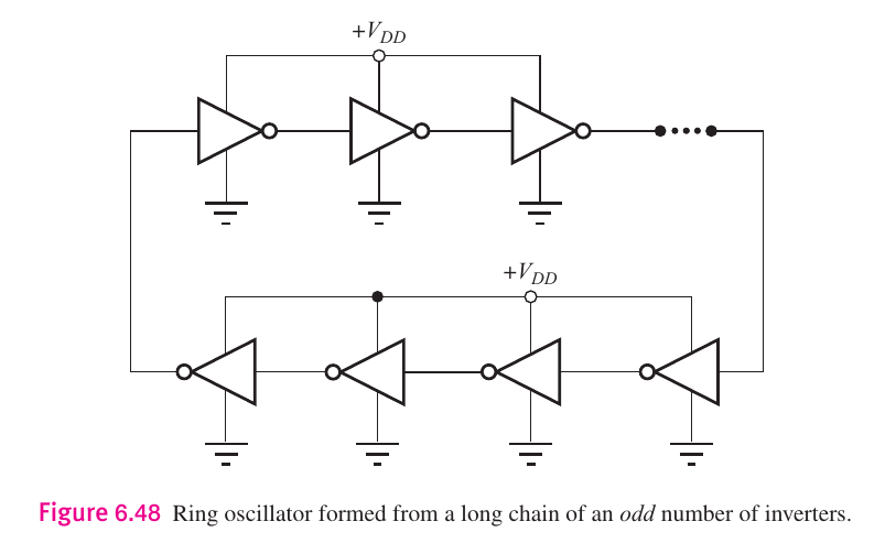
Adding the delays of each inverter from two round trips we get the result. For the first trip, since is given and required to be odd, then we add:
For the second run we get the opposite order of delays, as we are flipped:
Adding them together:
6.139
Given:
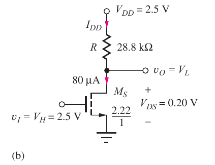
Given that we have a load of . For a resistive load we use:
Thus:
Thus: