Assignment 22 - MIDI out to STM32 Device
USB Setup Forum That Helped a Bit
- Experiment Design: Take in a USB input data, say MIDI data, from an external source (PC/Laptop/MIDI Device) and output
The device (STM) to be a USB Host, but what is a USB host?
Main Points on USB Hosting
There are multiple USB host types. Since we are doing a USB-type B from our device, and USB-type A to our STM, we want our STM to be an OTG A-host.
Some behaviors to note are that:
- The STM has a
OTG_HPRTstatus register for host port control, that - ... (really a lot of the behaviors are "as you need them" so follow the
OTG_FSprogramming model for whatever you need, and look up stuff as you go).
Initialization
When connecting:
- If an "A" plug is connected, then the device enters host mode, if "B" then enters device mode.
- You must follow the following to initialize the device in this way
OTG_GAHBCFG:- Global interrupt mask bit
OTG_GINTMSK = 1 - Empty the FIFO Rx bit via
RXFLVLwithin theOTG_GINTSTSregister. - Program the same Tx bit
TXFLVLin the same register.
- Global interrupt mask bit
OTG_GUSBCFG:- Enable some of
HNP, SRP OTG_FStimeout calibration field- USB turnaround time field (in
OTG_GUSBCFG)
- Enable some of
- Unmask
OTG_GINMSKand either choose to mask or not theOTGinterrupt and mode mismatch interrupt masks - Read from the
CMODbit inOTG_GINSTSto confirm that we are in the host mode (or device mode if you want that)
Host Initialization
You must:
- Program
HPRTINTin theOTG_GINTMSKregister to unmask - Set
OTG_HCFGregister to select full-speed host - Set
OTG_HPRTto 1, to driveV_BUSon the USB (we want to power it from here). - (continue from pg. 1782)
Channel Initialization
You'll need to setup a USB channel in order to read and write data over. See pg. 1783 for that.
Receiving Data Packets
See pg. 1784 and 1785 for read and write access to FIFOs per channel. The programming flowchart is essentially what code you want to have to setup your USB read/write functions.
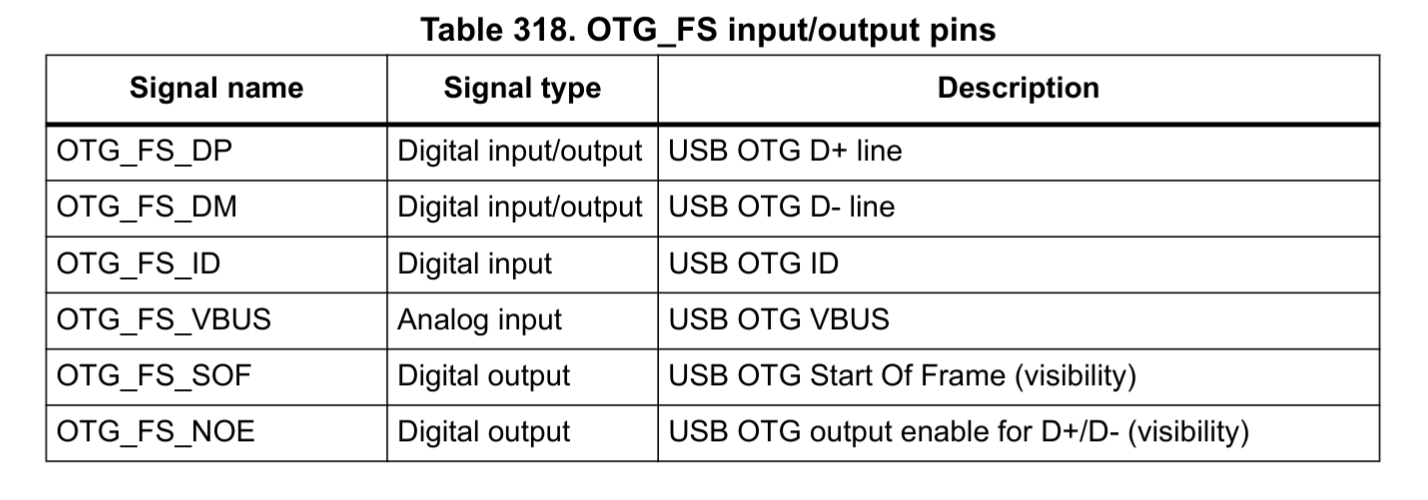
Setting up GPIO
By ![[datasheet_stm32l476rg.pdf#page=99]]
use the PA10-13 pins for connecting the USB-A side pins to, rather than the onboard usb (that's the debug USB). Via ![[datasheet_stm32l476rg.pdf#page=99]]
,